Flare Tip

Flare Tip

Definition(s)


Flare Tip

Part of the flare where fuel and air are mixed at the velocities, turbulence, and concentration required to establish and maintain proper ignition and stable combustion.

Source: API STD 521, Pressure-relieving and Depressuring Systems, Sixth Edition, January 2014. Global Standards
Flash

Flash

Definition(s)


Flash

A complete discharge of the cell between the thundercloud and ground (as it applies to cloud-to-ground lightning) (Uman, The Lightning Discharge, p. 10). Source: API RP 545 Recommended Practice for Lightning Protection of Aboveground Storage Tanks for Flammable or Combustible Liquids, First Edition, October 2009. Global Standards
Flash Point

Flash Point

Definition(s)


 Flash Point

The lowest temperature at which a flammable product emits enough vapor to form an ignitable mixture in air, (e.g. gasoline's flash point is about –45 °F, diesel's flash point varies from about 125 °F to 200 °F.)
  • NOTE: An ignition source is required to cause ignition above the flash point, but below the auto-ignition temperature.
Source: API 570, Piping Inspection Code: In-service Inspection, Rating, Repair, and Alteration of Piping Systems, Fourth Edition, February 2016, with Addendum May 2017. Global Standards  

Flashpoint

Lowest liquid temperature at which, under certain standardized conditions, a liquid gives off vapours in a quantity such as to be capable of forming an ignitable vapour/air mixture. [IEV 426-02-14]. Source: IEC 61892-7, Mobile and fixed offshore units – Electrical installations – Part 7: Hazardous areas. Global Standards

Flashpoint

"Flashpoint" means the minimum temperature at which a liquid gives off vapor within a test vessel in sufficient concentration to form an ignitable mixture with air near the surface of the liquid and shall be determined as follows: (A) For a liquid which has a viscosity of less than 45 SUS at 100°F. (37.8°C.), does not contain suspended solids, and does not have a tendency to form a surface film while under test, the procedure specified in the Standard Method of Test for Flashpoint by Tag Closed Tester (ASTM D-56-70) shall be used. (B) For a liquid which has a viscosity of 45 SUS or more at 100°F.(37.8°C.), or contains suspended solids or has a tendency to form a surface film while under test, the Standard Method of Test for Flashpoint by Pensky-Martens Closed Tester (ASTM D-93-7I) shall be used, except that the methods specified in Note 1 to Section 1.1 of ASTM D-93-71 may be used for the respective materials specified in the Note. (C) For a liquid that is a mixture of compounds that have different volatilities and flashpoints, its flashpoint shall be determined by using the procedure specified in paragraph (xxv) (A) or (B) of this section on the liquid in the form it is shipped. If the flashpoint, as determined by this test is 100°F. (37.8°C.) or higher, an additional flashpoint determination shall be run on a sample of the liquid evaporated to ninety (90) percent of its original volume, and the lower value of the two tests shall be considered the flashpoint of the material. (D) Organic peroxides, which undergo autoaccelerating thermal decomposition, are excluded from any of the flashpoint determination methods specified in this subparagraph. Source: State of Wyoming Occupational Safety and Health Rules and Regulations for Oil and Gas Well Drilling, Revised January 8, 2013. Regulations  

Flash Point

The minimum temperature of a liquid at which sufficient vapor is given off to form an ignitable mixture with air, near the surface of the liquid or within the vessel used, as determined by the test procedure and apparatus specified in NFPA 30. API RP 500, Recommended Practice for Classification of Locations for Electrical Installations at Petroleum Facilities Classified as Class I, Division 1 and Division 2, Third Edition, December 2012, Global Standards  

Flashpoint

Flashpoint means the temperature in degrees Celsius (closed cup test) at which a product will give off enough flammable vapour to be ignited, as determined by an approved flashpoint apparatus. Source: IMO MSC.1/Circ.1321, Guidelines for measures to prevent fires in engine-rooms and cargo pump-rooms, 11 June 2009, International Maritime Organization. Regulatory Guidance  

Flash Point

The lowest temperature at which the vapor pressure of the liquid is just sufficient to produce a flammable mixture at the lower limit of flammability. Source: API RP 14G, Recommended Practice for Fire Prevention and Control on Fixed Open-type Offshore Production Platforms: Upstream Segment, Fourth Edition, April 2007. Global Standards  

Flashpoint

Flashpoint is the temperature in degrees Celsius (closed cup test) at which a product will give off enough flammable vapour to be ignited, as determined by an approved flashpoint apparatus. <Chapter II-2, part A, regulation 3>. Source: IMO Resolution MSC.99(73), amendments to the International Convention for the Safety of Life at Sea, 1974, as amended, 5 December 2000, International Maritime Organization. Legislation
Flash Point or Flashpoint

Flash Point or Flashpoint

Definition(s)


Flash Point or Flashpoint

Temperature that a liquid releases sufficient vapor to form a mixture with air igniteable by a flame. Source: IADC UBO / MPD Glossary, December 2011. Global Standards
Flash Side

Flash Side

Definition(s)


Flash Side

Side containing residue (“flash”) from stamping, or the side with concave indentation. Source: API SPEC 13A, Specification for Drilling Fluids Materials, Eighteenth Edition, February 2010. Global Standards
Flashback

Flashback

Definition(s)


Flashback

Phenomenon occurring in a flammable mixture of air and gas when the local velocity of the mixture becomes less than the flame velocity, causing the flame to travel back through the mixture.

Source: API STD 521, Pressure-relieving and Depressuring Systems, Sixth Edition, January 2014. Global Standard

Flashback

Phenomenon occurring in a flammable mixture of air and gas when the local velocity of the combustible mixture becomes less than the flame velocity, causing the flame to travel back to the point of mixture. Source: API STD 521, Pressure-relieving and Depressuring Systems, Fifth Edition, January 2007 (Addendum May 2008). Global Standards 
Flashing

Flashing

Definition(s)


Flashing

When a pressure drop causes the fluid to become gas-liquid mixture that continues to flow within a line or vessel. Source: IADC UBO / MPD Glossary, December 2011. Global Standards
Flashpoint

Flashpoint

Definition(s)


Flash-point

"Flash-point" of any petroleum means the lowest temperature at which it yields a vapour which will give a momentary flash when ignited, determined in accordance with the provisions of Chapter II and the rules made thereunder. Source: The Petroleum Act, 1934 (Act No. 30 of 1934), India, 1934. Legislation

Flashpoint

Flashpoint is the temperature in degrees Celsius at which a product will give off enough flammable vapour to be ignited. Values given in the Code are those for a “closed-cup test” determined by an approved flashpoint apparatus. Source: Resolution MEPC.119(52), 2004 amendments to the International Code for the Construction and Equipment of Ships Carrying Dangerous Chemicals in Bulk (IBC Code), 15 October 2004. Regulatory guidance, International Maritime Organization
Flat Characteristic Curve

Flat Characteristic Curve

Definition(s)


Flat Characteristic Curve

Head developed at shut-off is only slightly greater than that at the design capacity. Source: IADC UBO / MPD Glossary, December 2011. Global Standards
Flaw

Flaw

Definition(s)


Flaw

An imperfection in a piping system usually detected by NDE which may or may not be a defect depending upon the applied acceptance criteria.

Source: API 570, Piping Inspection Code: In-service Inspection, Rating, Repair, and Alteration of Piping Systems, Fourth Edition, February 2016, with Addendum May 2017. Global Standards
FLD

FLD

Definition(s)


FLD

Full-length drifted. Source: API RP 5A5, Field Inspection of New Casing, Tubing, and Plain-end Drill Pipe, Reaffirmed August 2010. Global Standards  
Fleet Angle

Fleet Angle

Definition(s)


Fleet Angle (for riser tensioners)

In marine riser nomenclature, the angle between the vertical axis and a riser tensioner line or the hydraulic cylinder rod (for direct-acting tensioners) at the point where the line (rod) connects to the telescopic joint.

Source: API Specification 16Q, Design, Selection, Operation, and Maintenance of Marine Drilling Riser Systems, Second Edition, April 2017. Global Standards

Fleet Angle

In marine riser nomenclature, the fleet angle is the angle between the vertical axis and a riser tensioner line at the point where the line connects to the telescopic joint. See Figure 1.1. Source: API RP 16Q, Recommended Practice for Design, Selection, Operation and Maintenance of Marine Drilling Riser Systems, First Edition, November 1993 (Reaffirmed August 2001). Global Standards  

Fleet Angle

Angle between the vertical axis and a riser tensioner line at the point where the line connects to the telescopic joint. Source: ISO 13624-1:2009, Petroleum and natural gas industries – Drilling and production equipment – Part 1:Design and operation of marine drilling riser equipment. Global Standards
FLEMI

FLEMI

Definition(s)


FLEMI

Full-length electromagnetic inspection. Source: API RP 5A5, Field Inspection of New Casing, Tubing, and Plain-end Drill Pipe, Reaffirmed August 2010. Global Standards  
Flex Joint

Flex Joint

Definition(s)


Flex Joint

Ball joint. Source: API Specification 16Q, Design, Selection, Operation, and Maintenance of Marine Drilling Riser Systems, Second Edition, April 2017. Global Standards  

Flex Joint

Device(s) installed between the bottom of the diverter and the telescopic joint (upper flex or ball joint), in the top section of the LMRP (lower flex or ball joint), or under a keel joint (intermediate flex or ball joint, if used), to permit relative angular movement of the riser and reduce stresses due to vessel motion and environmental forces.
  • NOTE: Upper flex ball joint is sometimes called a diverter flex ball joint.
Source: API Specification 16Q, Design, Selection, Operation, and Maintenance of Marine Drilling Riser Systems, Second Edition, April 2017. Global Standards

Flex Joint

A steel and elastomer assembly having central through-passage equal to or greater in diameter than the riser bore that may be positioned in the riser string to reduce local bending stresses. Source: API RP 16Q, Recommended Practice for Design, Selection, Operation and Maintenance of Marine Drilling Riser Systems, First Edition, November 1993 (Reaffirmed August 2001). Global Standards  

Flex Joint

Laminated metal and elastomer assembly, having a central through-passage equal to or greater in diameter than the interfacing pipe or tubing bore, that is positioned in the riser string to reduce the local bending stresses. Source: API RP 17G, Recommended Practice for Completion/Workover Risers, Second Edition, July 2006 (Reaffirmed April 2011). Global Standards  

Flex Joint

Steel and elastomer assembly that has a central through-passage equal to or greater in diameter than the riser bore and that may be positioned in the riser string to reduce local bending stresses. Source: ISO 13624-1:2009, Petroleum and natural gas industries – Drilling and production equipment – Part 1:Design and operation of marine drilling riser equipment. Global Standards
Flex/Ball Joint

Flex/Ball Joint

Definition(s)


Flex/Ball Joint

Device(s) installed between the bottom of the diverter and LMRP joint, to permit relative angular movement of the riser, to reduce stresses due to vessel motion and environmental forces. Source: API STD 53, Blowout Prevention Equipment Systems for Drilling Wells, Upstream Segment, Fourth Edition, November 2012. Global Standards  

Flex/Ball Joint

A device installed directly above the subsea BOP stack and at the top of the telescopic riser joint to permit relative angular movement of the riser to reduce stresses due to vessel motions and environmental forces. Source: API RP 64, Recommended Practice for Diverter Systems Equipment and Operations, Second Edition, November 2001 (March 1, 2007). Global Standards  
Flexed

Flexed

Definition(s)


Flexed

Condition of a bow spring when a force three times the specified minimum restoring force (±5%) has been applied to it. Source: API SPEC 10D, Specification for Bow-String Casing Centralizers Upstream Segment, Sixth Edition, March 2002 (Reaffirmed August 2010). Global Standards
Flexibility Factor

Flexibility Factor

Definition(s)


Flexibility Factor

Ratio of the flexibility in bending of a component/fitting to that of the flexibility of a straight pipe of the same lamination, Young's modulus and thickness having a length corresponding to the developed length of the fitting. Source: ISO 14692-1:2017, Petroleum and natural gas industries — Glass-reinforced plastics (GRP) piping — Part 1: Vocabulary, symbols, applications and materials, Second Edition, August 2017. Global Standards
Flexible Flowline

Flexible Flowline

Definition(s)


Flexible Flowline

Flexible pipe, wholly or in part, resting on the seafloor or buried below the seafloor, and used in a static application. NOTE The term flowline is used in this document as a generic term for flexible flowlines. Source: API SPEC 17J, Specification for Unbonded Flexible Pipe, Third Edition, July 2008. Global Standards  
Flexible Joint

Flexible Joint

Definition(s)


Flexible Joint

Laminated metal and elastomer assembly, having a central through-passage equal to or greater in diameter than the interfacing pipe or tubing bore, that is positioned in the riser string to reduce the local bending stresses. Source: API Standard 2RD, Dynamic Risers for Floating Production Systems, Second Edition, September 2013. Global Standards
Flexible Pipe

Flexible Pipe

Definition(s)


Flexible pipe

Flexible pipe is characterized by a composite construction of layers of different materials, which allows large amplitude deflections without adverse effects on the pipe. This product may be delivered in one continuous length or joined together with connectors. Source: API RP 17A, Design and Operation of Subsea Production Systems—General Requirements and Recommendations, Fourth Edition, Reaffirmed 2011. Global Standards  

Flexible pipe

Assembly of a pipe body and end fittings where the pipe body is composed of a composite of layered materials that form a pressure-containing conduit and the pipe structure allows large deflections without a significant increase in bending stresses. NOTE Normally the pipe body is built up as a composite structure composed of metallic and polymer layers. The term “pipe” is used in this document as a generic term for flexible pipe. Source: API SPEC 17J, Specification for Unbonded Flexible Pipe, Third Edition, July 2008. Global Standards
Flexible Pipe System

Flexible Pipe System

Definition(s)


Flexible Pipe System

Fluid conveyance system for which the flexible pipe(s) is the primary component and which includes ancillary components attached directly or indirectly to the pipe. Source: API RP 17L2, Recommended Practice for Flexible Pipe Ancillary Equipment, First Edition, March 2013. Global Standards  

Flexible Pipe System

Fluid conveyance system for which the flexible pipe(s) is/are the primary component and which includes ancillary components attached directly or indirectly to the pipe. Source: API RP 17B, Recommended Practice for Flexible Pipe, Fourth Edition, July 2008. Global Standards
Flexible Riser

Flexible Riser

Definition(s)


Flexible Riser

Flexible pipe connecting a platform/buoy/ship to a flowline, seafloor installation, or another platform where the riser may be freely suspended (free, catenary), restrained to some extent (buoys, chains), totally restrained or enclosed in a tube (I- or J-tubes). Source: API SPEC 17J, Specification for Unbonded Flexible Pipe, Third Edition, July 2008. Global Standards
Flexible Riser Base Connection

Flexible Riser Base Connection

Definition(s)


Flexible riser base connection

Part of a riser base that forms the transition between the flexible pipe end fitting and the riser base structure. Source: API RP 17L2, Recommended Practice for Flexible Pipe Ancillary Equipment, First Edition, March 2013. Global Standards
FLMPI

FLMPI

Definition(s)


FLMPI

Full length magnetic particle inspection (wet or dry MPI). Source: API RP 5A5, Field Inspection of New Casing, Tubing, and Plain-end Drill Pipe, Reaffirmed August 2010. Global Standards  
Float Collar

Float Collar

Definition(s)


Float Collar

A short cylindrical section of steel which is placed in the casing string above the guide shoe. The float collar usually incorporates a bail or spring-loaded backpressure valve which prevents wellbore fluid from entering the casing while the pipe is lowered in the well. This makes the casing buoyant, thereby reducing the derrick stress while running casing. Source: API BULLETIN E3, Environmental Guidance Document: Well Abandonment and Inactive Well Practices for U.S. Exploration and Production Operations, First Edition, January 1993 (Reaffirmed June 2000). Global Standards  
Float Shoe

Float Shoe

Definition(s)


Float Shoe

A guide shoe run on the bottom of the casing string that incorporates a ball or spring-loaded backpressure valve which prevents wellbore fluid from entering the casing while the pipe is lowered in the well. Performs the same function as the float collar. Source: API BULLETIN E3, Environmental Guidance Document: Well Abandonment and Inactive Well Practices for U.S. Exploration and Production Operations, First Edition, January 1993 (Reaffirmed June 2000). Global Standards  
Floating Mud Cap Drilling

Floating Mud Cap Drilling

Definition(s)


Floating Mud Cap Drilling

A drilling technique used to drill without returns while sacrificial fluid is continuously pumped down drill string and the annulus to avoid all possibility of formation fluid migrating to the surface. Open-hole formation is taking all injected (sacrificial) fluid and drilled cuttings without surface pressure assistance.

Source: ABS Guide for Classification and Certification of Managed Pressure Drilling Systems, September 2017. Global Standards
Floating Pipe

Floating Pipe

Definition(s)


Floating Pipe

A surface pipe between the singlepoint mooring or buoy and the ship manifold. The floating pipe is normally permanently attached to the single-point mooring. 
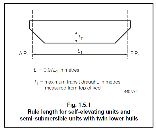
Source: Rules and Regulations for the Classification of Mobile Offshore Units, Part 3, Functional Unit Types and Special Features, June 2013, Lloyd’s Register, Global Standards
Floating Structure

Floating Structure

Definition(s)


Floating Structure

Structure where the full weight is supported by buoyancy. [ISO 19900:2002] NOTE The full weight includes lightship weight, mooring system pre-tension, riser pre-tension, operating weight, etc. Source: ISO 19901-7:2013, Petroleum and natural gas industries – Specific requirements for offshore structures – Part 7: Stationkeeping systems for floating offshore structures and mobile offshore units. Global Standards Source: ISO 19900:2013, Petroleum and natural gas industries – General requirements for offshore structures. Global Standards
Floating Vessel

Floating Vessel

Definition(s)


Floating Vessel

Installation which is floating and positioned relative to the sea bottom by station-keeping systems such as catenary mooring systems, vertical tendons, and dynamic positioning systems based on thrusters. Source: API Standard 2RD, Dynamic Risers for Floating Production Systems, Second Edition, September 2013. Global Standards

Floating Vessel

Buoyant installation that is floating and positioned relative to the sea bottom by station keeping systems. NOTE The following types of station-keeping systems are normally considered: catenary mooring systems and dynamic positioning systems based on thrusters. Combination of station-keeping systems can be considered. EXAMPLE Semi- submersible drilling vessels and drill ships. Source: API RP 17G, Recommended Practice for Completion/Workover Risers, Second Edition, July 2006 (Reaffirmed April 2011). Global Standards