Random Failure

Random Failure

Definition(s)


Random Failure

failure, occurring in a random way Note 1 to entry: A random failure may be time or demand dependent. Whether it occurs or not is not predictable with certainty but the corresponding failure rate (see 3.1.18) or probability of a failure due to demand (see 3.2.13) may be predictable and this allows probabilistic calculations. EXAMPLE Examples of failure mechanisms leading to unpredictable failure occurrence are: hardware random failures resulting from degradation mechanisms; human random failure resulting from error in routine operation, lack of attention, stress, tiredness, etc   Note 2 to entry: From the probabilistic point of view, the random failures are the contrary of systematic failures (see 3.2.17) which occur in a deterministic way (i.e. with a probability equal to 1) when some conditions are met. Source: ISO/TR 12489:2013(E) Reliability modelling and calculation of safety systems. Global Standards
Common Mode Failures

Common Mode Failures

Definition(s)


Common Mode Failures

failures of different items, occurring in the same way Note 1 to entry: Common mode failures may have different causes. Note 2 to entry: Common mode failures can be due to common cause failures Source: ISO/TR 12489:2013(E) Reliability modelling and calculation of safety systems. Global Standards
Failure Due to Demand

Failure Due to Demand

Definition(s)


Failure Due to Demand

failure occurring on demand γ, ψ failure of one item due to a change of its state triggered by an external event (the so-called “demand”) EXAMPLE 1 Obtaining 2 when launching a dice is an event occurring on demand. The probability of this event is 1/6. It does not depend on the elapsing time but only of the demand itself (i.e. the fact that the dice is launched). EXAMPLE 2 The failure of an electromechanical relay (e.g. rupture of the spring) when it changes state depends on the number of operations (cycles) rather on the operating time (see IEC 61810–2[49]) and this is the same for the failure of an electronic device due to over voltage when it is switched or the blocking of a diesel engine when it is started, etc.: these are typical examples of failures due to demands (or cycles). Note 1 to entry: In this Technical Report two kinds of demand are considered: the periodic tests and the demand for an actual safety action. The probability of a failure due to periodic test is a constant number noted γ and the probability of a failure due to one actual demand of the safety action is a constant number noted ψ. Over a given time interval, those probabilities of failure do not depend on the duration but on the number of demands or tests occurring within this interval. The use of γ and ψ is explained in 7.3. Note 2 to entry: This should not be confused with the “failure on demand” appearing in the term “probability of failure on demand” (see 3.1.14, Note 2 to entry) used in functional safety standards[2] for low demand mode safety systems. In those standards this means “failures likely to be observed when a demand occurs”. Source: ISO/TR 12489:2013(E) Reliability modelling and calculation of safety systems. Global Standards
Time-dependent Failure

Time-dependent Failure

Definition(s)


Time-dependent Failure

failure occurring with a probability depending of the time Note 1 to entry: The unreliability F(t) is a typical probability function describing time-dependent failures Source: ISO/TR 12489:2013(E) Reliability modelling and calculation of safety systems. Global Standards
Immediately Revealed Failure

Immediately Revealed Failure

Definition(s)


Immediately Revealed Failure

overt failure detected failure evident failure failure which is immediately evident to operations and maintenance personnel as soon as it occurs Note 1 to entry: The immediately revealed failures show themselves immediately, but the hidden failures which are quickly detected by specific diagnostic tests are generally considered as immediately revealed failures. Note 2 to entry: The repair of immediately revealed failures may begin immediately after they have occurred. Note 3 to entry: The failures which are detected by periodic tests are not considered as immediately revealed failures. Source: ISO/TR 12489:2013(E) Reliability modelling and calculation of safety systems. Global Standards
Catalectic Failure

Catalectic Failure

Definition(s)


Catalectic Failure

sudden and complete failure Note 1 to entry: This term has been introduced by analogy with the catalectic verses (i.e. a verse with seven foots instead of eight) which stop abruptly. Then, a catalectic failure occurs without warning and is more or less impossible to forecast by examining the item. It is the contrary of failures occurring progressively and incompletely. Note 2 to entry: Catalectic failures characterize simple components with constant failure rates (exponential law): they remain permanently “as good as new” until they fail suddenly, completely and without warning. Most of the probabilistic models used in reliability engineering are based on catalectic failures of the individual component of the system under study (e.g. Markovian approach). Source: ISO/TR 12489:2013(E) Reliability modelling and calculation of safety systems. Global Standards
Systemic Failure

Systemic Failure

Definition(s)


Systemic Failure

holistic failure failure at system level which cannot be simply described from the individual component failures of the system Note 1 to entry: Systemic/holistic principles have been concisely summarized by Aristotle by “The whole is more than the sum of its parts”. Note 2 to entry: Components have only failure modes. Those failure modes become dangerous, safe or spurious only when the components are implemented into a safety “system”. This is why dangerous, safe or spurious failures are typical systemic failures. For example the failure “fail to close” of a valve is dangerous only if it belongs to a safety system closing this valve on demand. Otherwise this failure mode does not matter. Note 3 to entry: “Systematic” failures (i.e. occurring in a deterministic way when given conditions are encountered, see 3.2.17) and “systemic” failures should not be confused. Source: ISO/TR 12489:2013(E) Reliability modelling and calculation of safety systems. Global Standards  

Systemic Failure

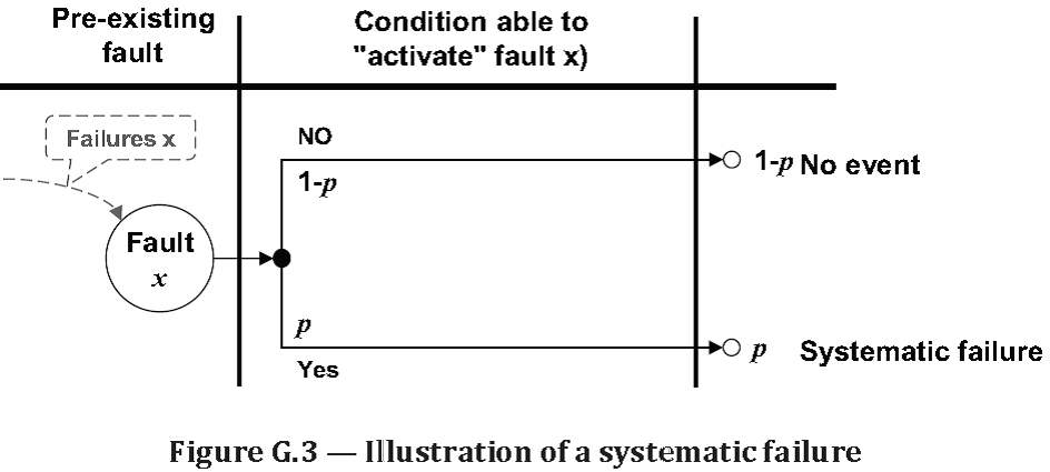
failure that consistently occurs under particular conditions of handling, storage or use Note 1 to entry: The cause of a systematic failure originates in the specification, design, manufacture, installation, operation or maintenance. Its occurrence is precipitated by particular conditions of handling, storage, use or maintenance (see Figure G.3) Note 2 to entry: Corrective maintenance without modification will usually not eliminate the failure cause. Note 3 to entry: A systematic failure can be reproduced by deliberately applying the same conditions, e.g. in verifying the failure cause (from IEC 60050–191 ed3[14]). Systematic failures are non-random failures (see 3.2.16). Note 4 to entry: In operation, a systematic failure is a manifestation of a systematic fault (i.e. a pre-existing state of the system). Note 5 to entry: The software systematic failures, called “bugs”, are example of systematic failures: they are due to pre-existing bugs (i.e. faults) and they occur when the input data activate them. Note 6 to entry: Systematic and systemic (which means “at system level”) failures (see 3.2.8) should not be confused. [SOURCE: IEC 60050‑191]   FIG.G3 Source: ISO/TR 12489:2013(E) Reliability modelling and calculation of safety systems. Global Standards
Critical Safe Failure

Critical Safe Failure

Definition(s)


Critical Safe Failure

spurious failure of a safety system, due to safe failure(s) of its component(s), triggering the safety action and leading to a spurious safety action Note 1 to entry: The concept of critical safe failure is illustrated in Figure B.1. Note 2 to entry: This is a systemic failure in relationship with a given safety action performed by the safety system. This concept is irrelevant for an individual item on the shelves. Note 3 to entry: The same failure of a component belonging to a safety system may be safe or spurious (critical safe) depending of the system state from which it occurs (e.g. the safe failure of a sensor belonging to 2oo3 is only safe when it occurs in 1st position. It is critical when it occurs in 2nd position).   fb1 Source: ISO/TR 12489:2013(E) Reliability modelling and calculation of safety systems. Global Standards
Spurious Failure

Spurious Failure

Definition(s)


Spurious Failure

failure triggering an action in an untimely manner Note 1 to entry: Critical safe failures (see Figure B.1) are the typical spurious failures related to safety systems. Note 2 to entry: A spurious failure does not necessarily imply a spurious trip (3.4.14) but a spurious trip is always the result of a spurious failure.   fb1 Source: ISO/TR 12489:2013(E) Reliability modelling and calculation of safety systems. Global Standards
Safe Failure

Safe Failure

Definition(s)


Safe Failure

failure of a safety system which tends to favour a given safety action Note 1 to entry: The concept of safe failure is illustrated in Figure B.1. Note 2 to entry: A failure is safe only with regard to a given safety function. This is a systemic failure in relationship with a given safety action performed by the safety system. This concept is irrelevant for an individual item on the shelves. Note 3 to entry: The non-critical safe failures basically increase the probability of success of the safety function. The critical safe failures initiate the related safety actions when this is not needed (see spurious failures).   fb1 Source: ISO/TR 12489:2013(E) Reliability modelling and calculation of safety systems. Global Standards
Critical Dangerous Failure

Critical Dangerous Failure

Definition(s)


Critical Dangerous Failure

dangerous failure leading to the complete inhibition of the safety action (i.e. leading to a dangerous situation for the protected system) Note 1 to entry: This is a systemic failure in relationship with a given safety action performed by the safety system. Therefore this concept is irrelevant for an individual item on the shelves. Note 2 to entry: The same failure of a component belonging to a safety system with internal redundancy may be dangerous or critical dangerous depending on the system state from which it occurs. Note 3 to entry: The critical dangerous failures that are undetected (e.g. those revealed by periodic tests) are sometimes called safety critical failures (cf. ISO 14224[15]). The equipment subject to such potential failures can be identified within a plant and monitored, and the ratio between the number of safety critical failures detected by periodic tests and the corresponding number of tests performed (commonly called “ failure fraction”) is being used for that purpose. This indicator of the average unavailability (PFDavg) due to dangerous undetected failures is established by using test reports. It is important not to mix such failure fraction with other reliability terms. Source: ISO/TR 12489:2013(E) Reliability modelling and calculation of safety systems. Global Standards
Dangerous Failure

Dangerous Failure

Definition(s)


Dangerous Failure

unsafe failure failure of a safety system which tends to impede a given safety action Note 1 to entry: This is a systemic failure in relationship with a given safety action performed by the safety system. Therefore this concept is irrelevant for an individual item on the shelves. Note 2 to entry: See Figure B.1.   fb1 Source: ISO/TR 12489:2013(E) Reliability modelling and calculation of safety systems. Global Standards
Failure Classification

Failure Classification

Definition(s)


Failure Classification

Explanations about the various states and the various failures of a safety system are developed in Annex B. Source: ISO/TR 12489:2013(E) Reliability modelling and calculation of safety systems. Global Standards
Restoration Rate

Restoration Rate

Definition(s)


Restoration Rate

μc onditional probability per unit of time that the restoration of a failed item ends between t and t+dt, provided that it was not finished over [0, t] Note 1 to entry: The following relationship holds when the restoration rate is constant: MTTRes = 1/μ. Note 2 to entry: The “restoration” rate is in relationship with the restoration time. Similarly the “repairing” rate can be defined in relationship with the “overall repairing” time and the “active repair” rate in relationship with the “active repair” time. Note 3 to entry: The restoration rate has the same mathematical properties for the restoration as the failure rate for the failures. Source: ISO/TR 12489:2013(E) Reliability modelling and calculation of safety systems. Global Standards
Mean Time to Demand

Mean Time to Demand

Definition(s)


Mean Time to Demand

expected time before the demand on the safety system occurs. Source: ISO/TR 12489:2013(E) Reliability modelling and calculation of safety systems. Global Standards
Maximum Permitted Repair Time

Maximum Permitted Repair Time

Definition(s)


Maximum Permitted Repair Time

MPRT maximum time allowed to repair a fault before undertaking an action to make the risk disappearing EXAMPLE When a dangerous fault is revealed for a safety system operating in demand mode, it may be decided to reach a safe state when a maximum duration has elapsed: a MPRT of 8 h means, for example, that if the repair is not completed after 8 h, the process is shut down. Then a safe state is reached, the fault is no longer dangerous, and it is not necessary to take into account the remaining time spent to complete the repair. This is illustrated in Figure 6, Figure 7 and Figure B.1. When the fault may result of several failure modes, the MPRT allows to repair those within short MRT without shutdown of the process. Note 1 to entry: When a MPRT is defined as a maintenance procedure it is necessary to take it into consideration for the probabilistic calculations of hazardous events. Reciprocally it is necessary that this MPRT be respected during the actual repair actions in order to keep the probabilistic calculations valid. Note 2 to entry: The role of the MPRT is close to the role of the MTTS (see 0). The difference is that the MPRT is a maximum duration allowed to reach a safe state and the MTTS is the average duration needed to reach the safe state when a dangerous fault is revealed (see Figure 6 and Figure 7). The methods developed in this Technical Report have been focused on random repair values (MTTRes, MRT, MTTS) rather than on deterministic values (MPRT), but the MPRT can be easily handled by using Petri nets and Monte Carlo simulations.   FIG.6   FIG.7   FIGUREB.1 Source: ISO/TR 12489:2013(E) Reliability modelling and calculation of safety systems. Global Standards
Mean Time to Safe State

Mean Time to Safe State

Definition(s)


Mean Time to Safe State

MTTS expected time needed for the protected installation to reach a safe state after a dangerous failure of a safety system has been detected EXAMPLE When a dangerous fault is revealed for a safety system operating in demand mode, it may be decided to reach a safe state rather to undertake the repair of the fault and this may take some time: a MTTS of 8 h means, for example, that, on average, 8 h are needed to shut down the process. After the shut down, a safe state is reached, the fault is no longer dangerous and it is not necessary to take into account the remaining time spent to complete the repair. This is illustrated in Figure 6, Figure 7 and Figure B.1. Note 1 to entry: When the MTTS is defined as a maintenance procedure it is necessary to take it into consideration for the probabilistic calculations of hazardous events. In this case the MTTS replaces the MRT (see 3.1.33) with regard to the probabilistic calculations. Reciprocally it is necessary to verify that this MTTS is respected during the actual repair actions in order to keep the probabilistic calculations valid. Note 2 to entry: The role of the MTTS is close to the role of the MPRT. The difference is that the MPRT is a maximum duration allowed to reach a safe state when the MTTS is the average of the random duration of the TTS needed to reach the safe state when a dangerous fault is revealed (see Figure 6 and Figure 7). The methods developed in this Technical Report have been focused on average random values (MTTRes, MRT, MTTS) rather than on deterministic values (MPRT), but the MPRT can be easily handled by using Petri nets and Monte Carlo simulations.   FIG.6   FIG.7   FIGUREB.1 Source: ISO/TR 12489:2013(E) Reliability modelling and calculation of safety systems. Global Standards
Mean Fault Detection Time

Mean Fault Detection Time

Definition(s)


Mean Fault Detection Time

MFDT expected time needed to detect a fault Note 1 to entry: The MFDT is the time a) in Figure 5, Figure 6 and Figure 7. Note 2 to entry: The MFDT is equal to zero for immediately revealed failure; (see Figure 6) generally negligible for quickly detected failures; (see Figure 6) depending of the test policy for the hidden failures. In this case it may be the main part of the item down time (see Figure 7). Note 3 to entry: The MFDT used in this Technical Report should not be mixed-up with the mean fractional dead time which has the same acronym.   FIG.5   FIG.6   FIG.7 Source: ISO/TR 12489:2013(E) Reliability modelling and calculation of safety systems. Global Standards
Mean Active Repair Time

Mean Active Repair Time

Definition(s)


Mean Active Repair Time

expected active repair time Note 1 to entry: The MART is the expected effective time to repair c, (see Figure 5, Figure 6 and Figure 7). FIG.5   FIG.6   FIG.7 Source: ISO/TR 12489:2013(E) Reliability modelling and calculation of safety systems. Global Standards
Mean Overall Repairing Time

Mean Overall Repairing Time

Definition(s)


Mean Overall Repairing Time

MRT expected time to achieve the following actions: • the time spent before starting the repair b; and, • the effective time to repair c; and, • the time before the component is made available to be is put back into operation d Note 1 to entry: See Figure 5, Figure 6 and Figure 7. Note 2 to entry: The terms “repair”, “repairable”, “repaired” used in this Technical Report, unless otherwise specified, are related to the overall repairing time (see Figure 5). Note 3 to entry: When a safety system operating in demand mode is faulty, the risk disappears as soon as the protected installation is placed in a safe state (e.g. stopped). In this case (see Figure 6 and Figure 7) the MTTS replaces the MRT (see 3.1.36) with regard to the probabilistic calculations. Note 4 to entry: This definition is in line with IEC 61508[2] but not with IEC 60050–191.[14].   FIG.5   FIG.6   FIG.7 Source: ISO/TR 12489:2013(E) Reliability modelling and calculation of safety systems. Global Standards
Mean Time to Restoration

Mean Time to Restoration

Definition(s)


Mean Time to Restoration

MTTRes expected time to achieve the following actions: (see Figure 5, Figure 6 and Figure 7): • the time to detect the failure a; and, • the time spent before starting the repair b; and, • the effective time to repair c; and, • the time before the component is made available to be put back into operation d   Note 1 to entry: Figure 5 illustrates how the times a, b, c and d defined in the IEC 61508[2] standard are linked to the delays defined in the IEC 60050–191[14] standard. Time b starts at the end of a; time c starts at the end of b; time d starts at the end of c. Note 2 to entry: Figure 5, Figure 6 and Figure 7 can be used to understand the differences between the definitions of MTTRes, MRT and MART used in this Technical Report. Note 3 to entry: The MTTRes is linked to the MRT and the MFDT by the following formula: MTTRes = MFDT + MRT.   FIG.5     FIG.6     FIG.7 Source: ISO/TR 12489:2013(E) Reliability modelling and calculation of safety systems. Global Standards    
Mean Down Time

Mean Down Time

Definition(s)


Mean Down Time

expectation of the down time Note 1 to entry: See Figure 3 and also ISO 14224[15] or IEC 60050–191[14] for definitions of up time and down time. [SOURCE: IEC 60050 −191] FIG.3 Source: ISO/TR 12489:2013(E) Reliability modelling and calculation of safety systems. Global Standards
Mean Up Time

Mean Up Time

Definition(s)


Mean Up Time

expectation of the up time Note 1 to entry: See Figure 3 and also ISO 14224[15] or IEC 60050–191[14] for definitions of up time and down time. [SOURCE: IEC 60050 −191] Source: ISO/TR 12489:2013(E) Reliability modelling and calculation of safety systems. Global Standards
Average Hazardous Event Frequency

Average Hazardous Event Frequency

Definition(s)


Average Hazardous Event Frequency

average accident frequency Φ(t ,t ) 1 2 , Φ(T) , Φ average frequency as 3.1.23 related to of the hazardous event (or to the accident) Source: ISO/TR 12489:2013(E) Reliability modelling and calculation of safety systems. Global Standards
Hazardous Event Frequency

Hazardous Event Frequency

Definition(s)


Hazardous Event Frequency

Φ(t) failure frequency as 3.1.23 related to the hazardous event (or to the accident) Source: ISO/TR 12489:2013(E) Reliability modelling and calculation of safety systems. Global Standards
Probability of Failure Per Hour PFH

Probability of Failure Per Hour PFH

Definition(s)


Probability of Failure Per Hour PFH

average failure frequency as 3.1.23 in the functional safety standard terminology (e.g. IEC 61508[2] or IEC 61511[3]) Note 1 to entry: The old meaning “Probability of Failure per Hour” is obsolete and replaced by “average failure frequency”. Nevertheless PFH is still in use to keep the consistency with the previous versions of functional safety standards. Source: ISO/TR 12489:2013(E) Reliability modelling and calculation of safety systems. Global Standards
Average Failure Frequency

Average Failure Frequency

Definition(s)


Average Failure Frequency

w(t1,t2) , w T ( ), w average value of the time-dependent failure frequency over a given time intervalaverage failure frequency Source: ISO/TR 12489:2013(E) Reliability modelling and calculation of safety systems. Global Standards
Failure Frequency

Failure Frequency

Definition(s)


Failure Frequency

3.1.22 unconditional failure intensity w(t) conditional probability per unit of time that the item fails between t and t+dt, provided that it was working at time 0 failure frequency Source: ISO/TR 12489:2013(E) Reliability modelling and calculation of safety systems. Global Standards
Vesely Failure Rate

Vesely Failure Rate

Definition(s)


Vesely Failure Rate

conditional failure intensity λV(t) conditional probability per unit of time that the item fails between t and t+dt, provided that it was working at time 0 and at time t Vesely failure rate Source: ISO/TR 12489:2013(E) Reliability modelling and calculation of safety systems. Global Standards
Asymptotic Failure Rate

Asymptotic Failure Rate

Definition(s)


Asymptotic Failure Rate

3.1.20 λ as limit, when it exists, of the failure rate λ(t) when t goes to infinity asymptotic failure rate fig.32   fig.33   fig34 Source: ISO/TR 12489:2013(E) Reliability modelling and calculation of safety systems. Global Standards